
How to design sheet metal parts for laser cutting
A clean file is the difference between a quote that lands in seconds and one that bounces back for edits. Follow these guidelines and your parts will move through auto-quoting and onto the cut floor without a human touching them.
Best file formats for online laser cutting
RapidFab's instant-quote system reads 2D and 3D CAD natively. Submit your geometry in one of these formats, with your blueprint attached as supporting documentation for any callouts the geometry alone can't carry.
| Format | Extension | Notes |
|---|---|---|
| STEP (preferred) | .step · .stp | 3D solid model. Preferred for parts with bends or features that benefit from the full model. |
| DXF | .dxf | 2D flat pattern. Ideal for flat sheet parts. Use 1:1 scale, single layer, closed contours. |
| PDF blueprint | .pdf | Attach alongside your CAD as supporting documentation. We pull every callout — dimensions, tolerances, GD&T, notes block. |
What we don't accept
- STL / mesh files — convert to STEP first
- Raster images (JPG, PNG, TIFF, BMP) — vectorize before upload
- Native CAD assembly files with multiple parts — submit one part per file
File requirements at a glance
The short version
- Geometry is at 1:1 scale, in inches or millimeters (no other units)
- File contains the cut path only — no dimensions, notes, borders, or title blocks
- All text is converted to outlines / shapes
- Stencil-style cutouts use bridges so islands don't fall out
- Holes and slots are at least 50% of material thickness
- No overlapping, intersecting, or duplicate lines
- All shapes are closed contours — no open paths or stray points
Artwork must be at 1:1 scale
Submit your geometry at the exact size you want it cut. Auto-quote reads the geometry, not the dimensions you've drawn next to it. If your file was converted from a raster image, verify dimensions by printing at 100% before uploading.
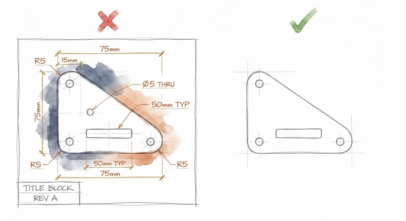
DXF files should contain the cut path only
Strip out drawing borders, title blocks, dimension annotations, leader lines, and any notes. The cut path is what the laser follows — anything else either gets cut by mistake or slows down auto-quote while it filters noise. Notes and tolerances belong on your blueprint, attached as supporting documentation.
Convert all text to outlines
The laser can't read live text — it follows vector paths. In Illustrator this is "Create Outlines"; in Fusion / SolidWorks it's "Sketch from Text" or "Convert to Spline." If hovering your cursor lets you edit a character, it's still live text and won't cut.
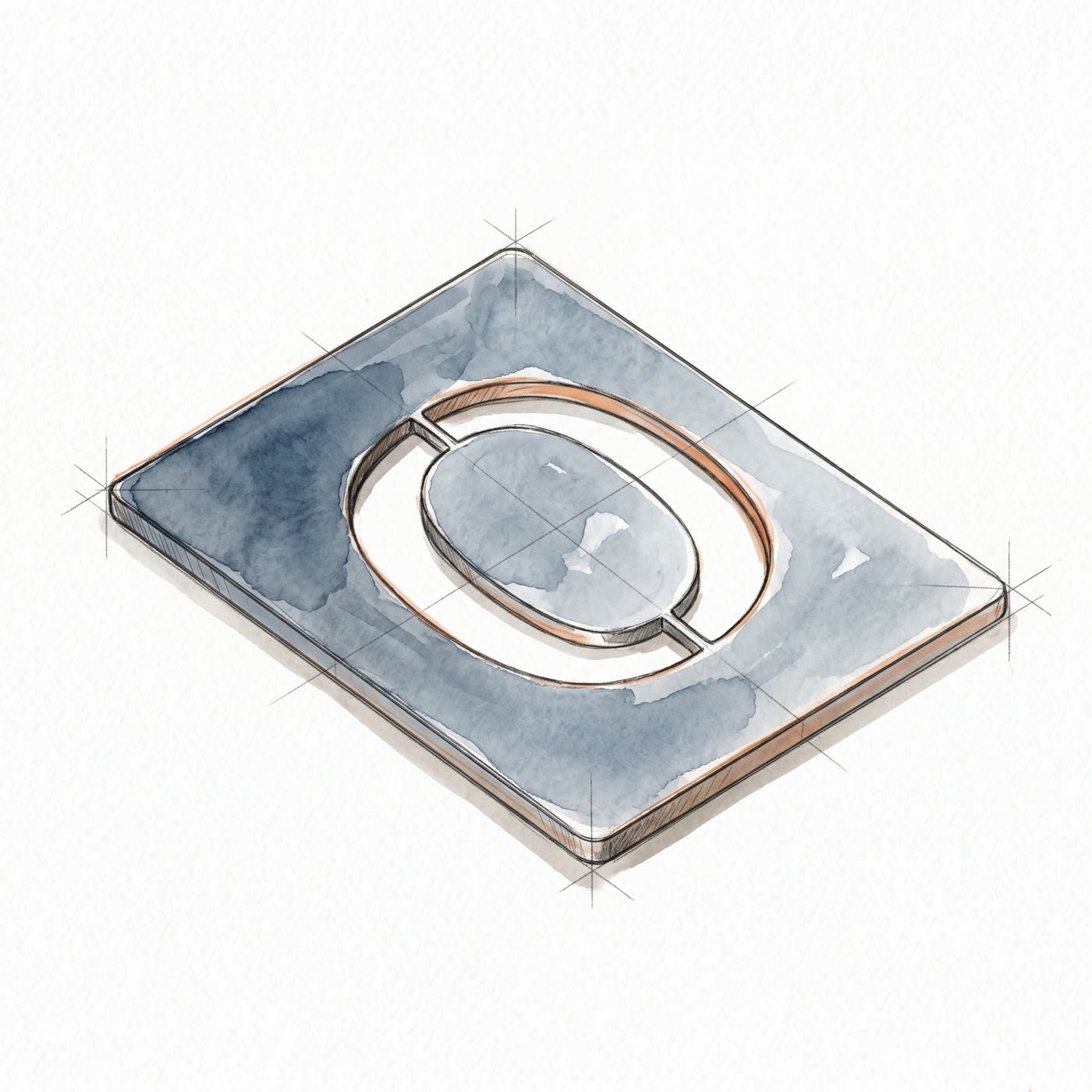
Stencil-style cutouts need bridges
Letters like O, A, D, R, and shapes that fully enclose an island will drop the inner piece during cutting. Add bridges to retain those islands, or treat the design as a stencil from the start.
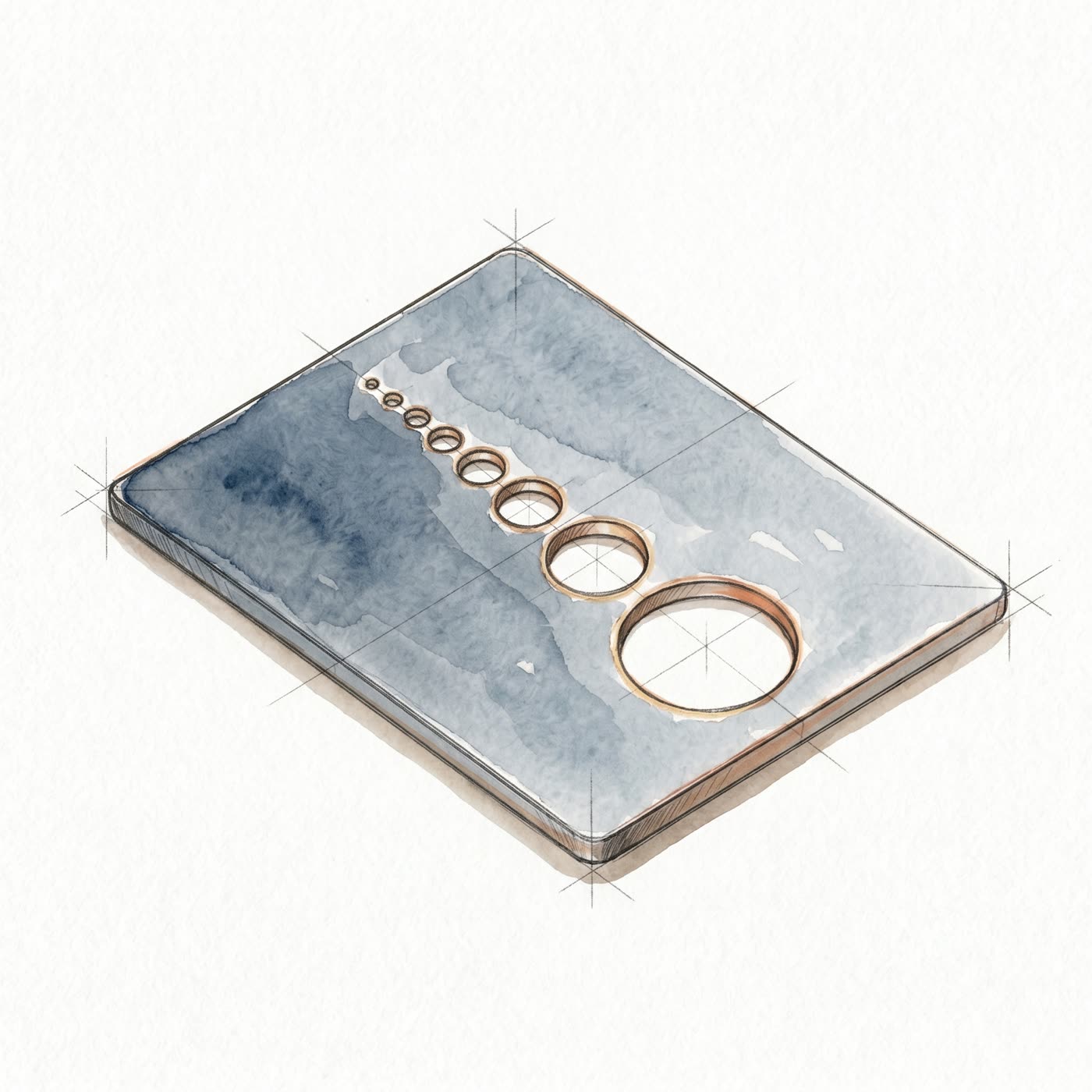
Minimum hole and cutout size
The laser pierces the material to start a cut, and that pierce needs room. As an industry rule of thumb, any hole, slot, or interior cutout should be at least 50% of the material thickness. So for 0.060″ material the minimum hole is roughly 0.030″. For tighter holes (smaller than ~50% thickness), use drilled or punched features instead.
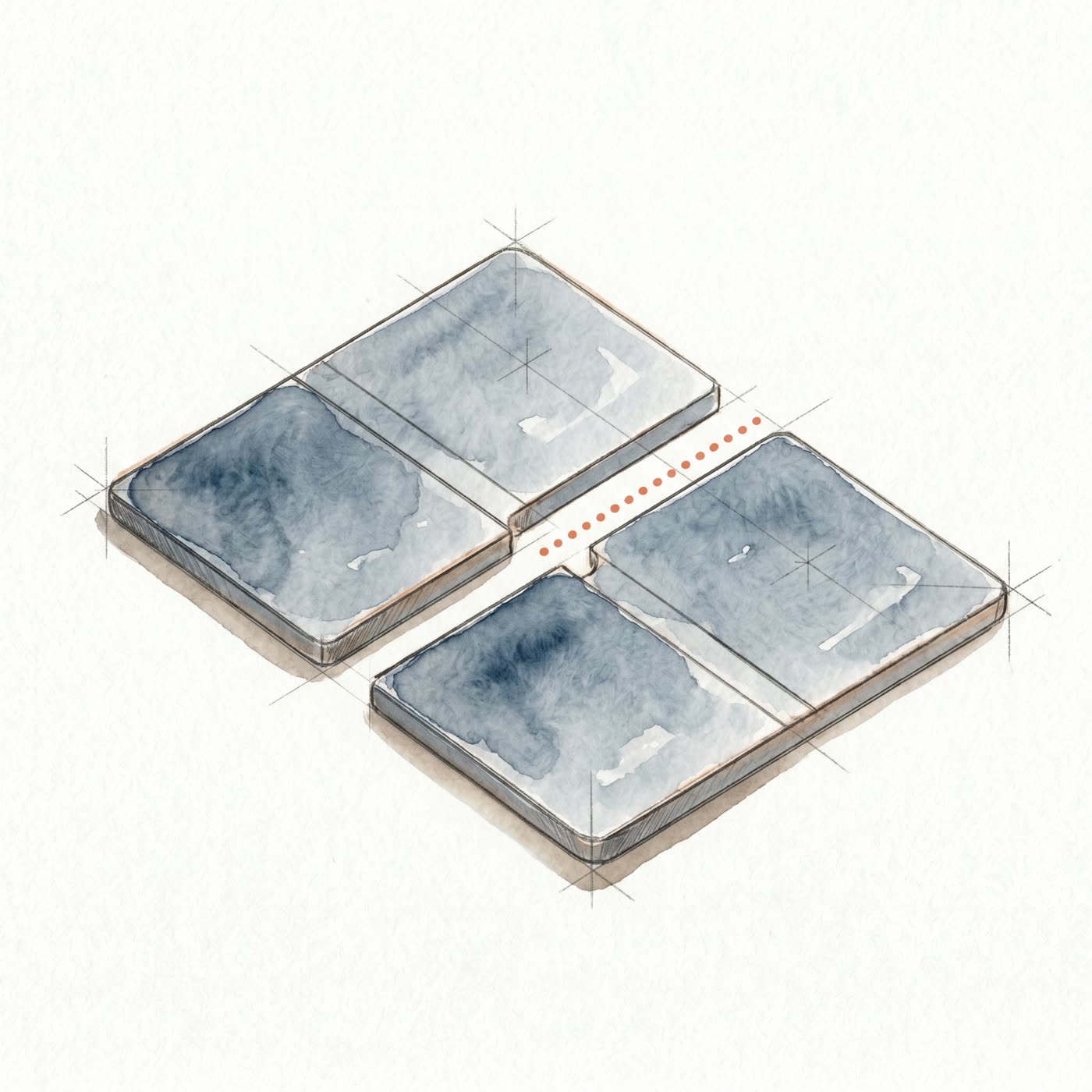
Avoid intersecting or shared lines
Each cut should have a single, unambiguous path. Overlapping lines, shared edges between parts, or two shapes touching along an edge create double-cuts and orphan geometry that auto-quote will reject. Switch to outline / wireframe view in your CAD before exporting to spot these.
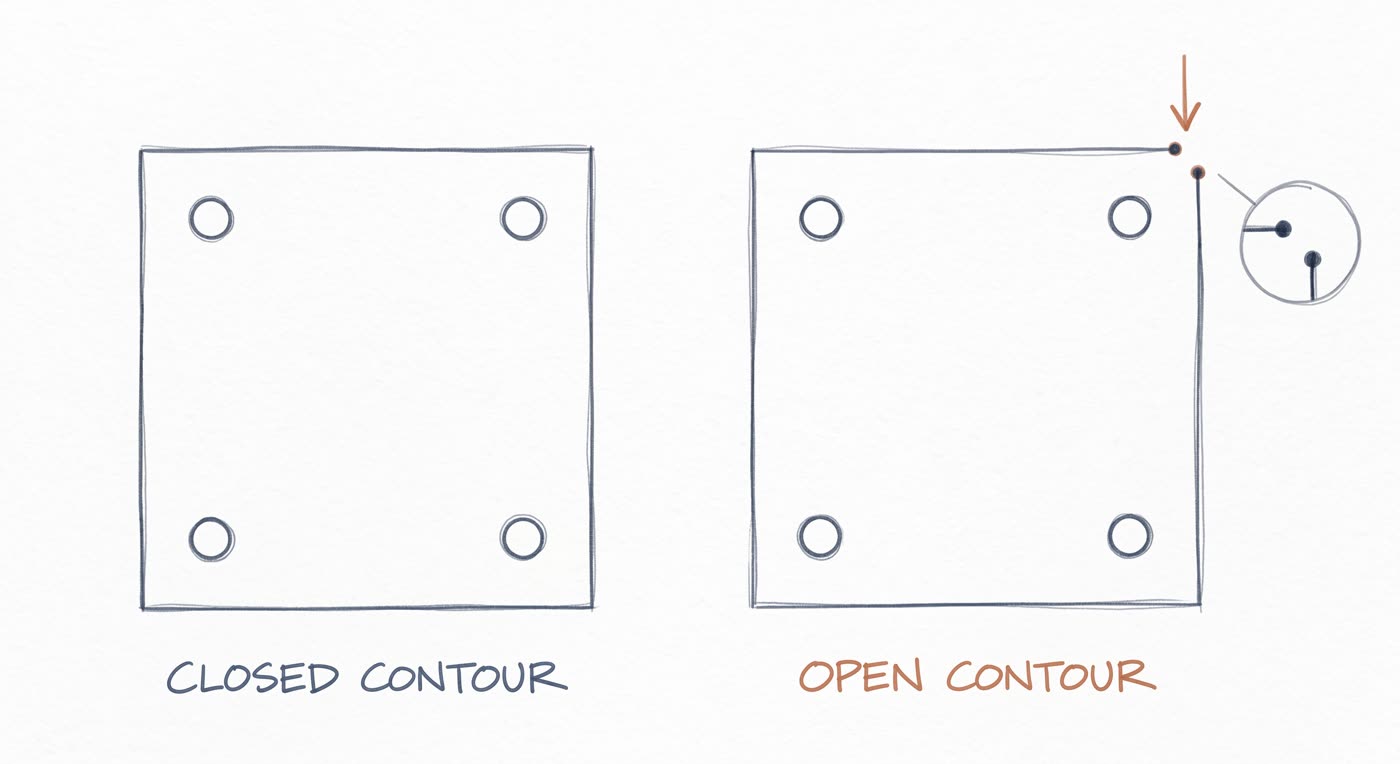
All DXF shapes must be closed contours
If a path starts but never closes back on itself, the laser keeps going past where you meant to stop. Run a "join" or "close all" operation on your geometry before export, and view in wireframe mode to catch any open endpoints.
Bending guidelines
Parts that ship to our press brake follow a few rules of thumb. These are industry standards and a safe starting point — call them out on your blueprint if you need anything tighter.
| Feature | Rule of thumb |
|---|---|
| Minimum inside bend radius | 1× material thickness for mild steel and aluminum; up to 2× for stainless and harder alloys |
| Minimum flange length | 4× material thickness + bend radius (so a 0.060″ sheet wants at least ~0.30″ of flange) |
| Hole-to-bend distance | At least 2.5× material thickness + bend radius — closer and the hole will distort |
| Bend relief on cutouts adjacent to a bend | Slot at least 1× material thickness wide and 1× bend radius deep |
| K-factor (default) | 0.40 for air-formed bends — override on your blueprint if you have a measured value |
| Bend-to-bend distance | At least 6× material thickness between parallel bends |
Important note
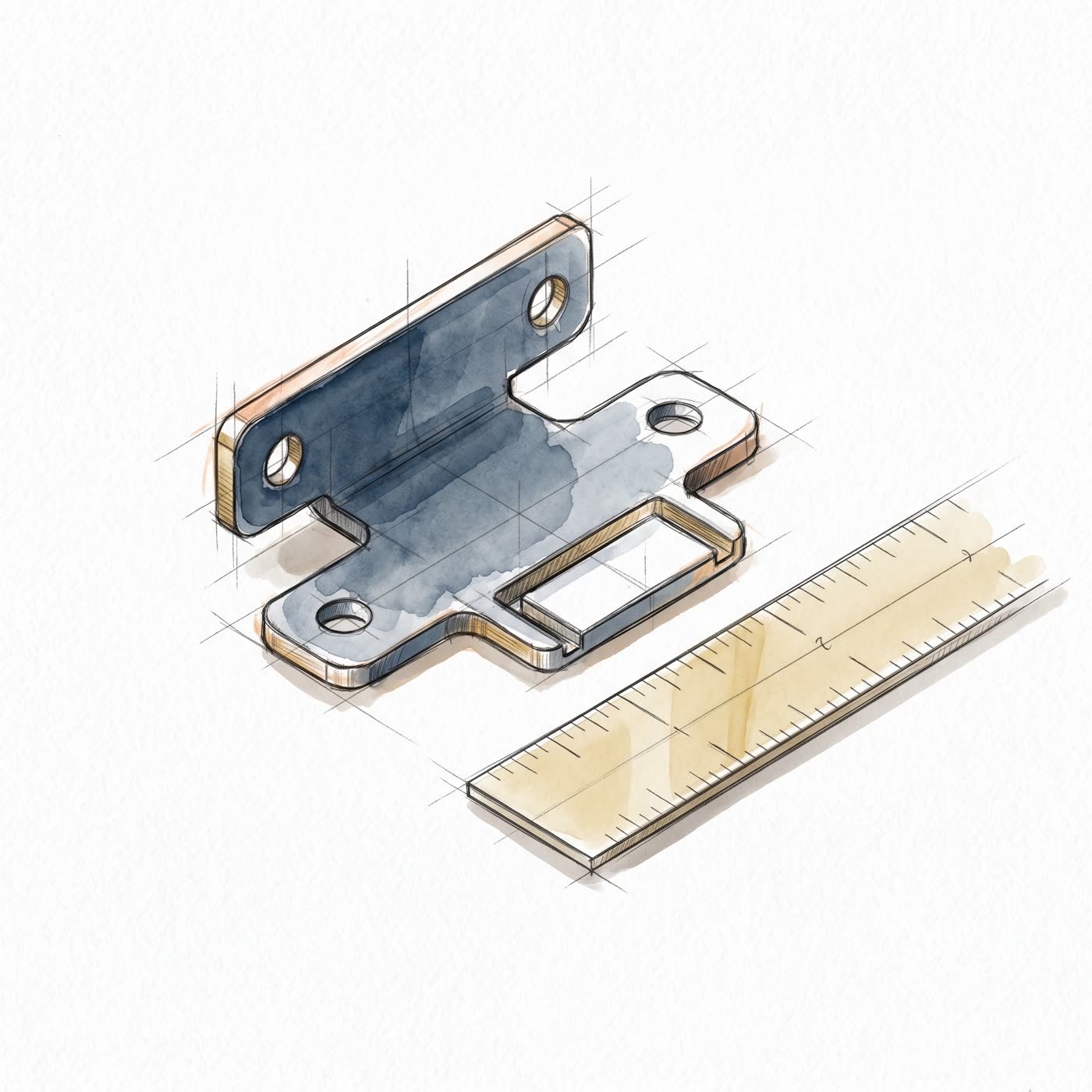
- STEP files are required for any bent geometry. If you submit a flat DXF, you'll get a flat part — we don't bend DXF-based parts.
- Bend angle tolerances are ±1°, and they don't get any tighter regardless of what tolerances might be called out on your print.
Materials & capabilities
RapidFab runs a 6 kW fiber laser across steel, aluminum, and stainless — up to 1″ on carbon and stainless, 0.75″ on aluminum — with press brake forming on the same production floor.
| Material | Thickness range | Notes |
|---|---|---|
| Carbon steel (A36, CRS, HRP&O) | 0.024″ – 1.000″ | Most common; widest stock availability |
| Stainless steel (304, 316) | 0.024″ – 1.000″ | 304 is the default; specify 316 on the blueprint if marine / food grade |
| Aluminum (5052, 6061) | 0.025″ – 0.750″ | 5052 for forming, 6061 for structural |
Need an exotic alloy, a thicker plate, or a polished finish? Drop it on your quote and note the material in the blueprint — we'll source it.
Pre-flight checklist
- File is a STEP, DXF, or PDF (with CAD attached)
- Geometry is at 1:1 scale, in inches or millimeters
- File contains the cut path only — no borders, title blocks, dimensions, or leaders
- All text has been converted to outlines
- Stencil cutouts have bridges
- Every hole and slot is at least 50% of the material thickness
- No intersecting, overlapping, or shared lines between parts
- All shapes are closed contours
- One part per file (assemblies are split before upload)
- Material, thickness, finish, and tolerances are called out on the blueprint
Ready to drop in your parts?
Upload your STEPs, DXFs, and blueprints. Up to 100 parts auto-quoted in minutes.
Get parts →