
How to design parts for laser tube cutting
Tube cutting is different from flat sheet — one part per file, full-depth cuts only, and the tube has to be modeled at the stock you're ordering. Get these right and your tube parts move through auto-quote in seconds.
Tube profiles we cut
RapidFab's tube laser handles round, square, and rectangular profiles up to 8″ outside diameter and 30 feet long. Complex 3D features — slots, holes, notches, mitered joints, weld-prep ends — happen in a single setup.
Best file formats for tube
Tubes need 3D CAD — there's no flat-pattern equivalent that captures features wrapping around the section. Submit one of these and attach a blueprint as supporting documentation.
| Format | Extension | Notes |
|---|---|---|
| STEP (preferred) | .step · .stp | The standard for tube cutting. Exports cleanly from Fusion, SolidWorks, Inventor, Onshape, NX. |
| PDF blueprint | .pdf | Attach alongside your STEP. We pull every callout — material, OD, wall, length tolerance, weld-prep angle, notes block. |
What we don't accept for tube
- Flat DXF patterns — the tube laser needs the 3D model
- Mesh / STL — convert to a solid STEP first
- Assemblies with more than one tube — one tube per file
- Files where the tube isn't modeled as a hollow tube (don't submit a solid bar)
File requirements at a glance
The short version
- One tube part per file — no assemblies
- Tube modeled at the stock size you're ordering (OD × wall × length)
- 1:1 scale, inches or millimeters
- All cuts are perpendicular to the tube surface and full-depth
- No multi-axis cuts, no blind features, no taps, no countersinks (those happen as secondary ops)
- Square / rect external corner radius modeled per the rule below
- Tube modeled along the Y axis
- Bridges added if cutouts would drop a feature
One tube part per file
Each STEP file should contain exactly one tube. Assemblies — even simple ones with two tubes meeting at a joint — will not auto-quote. Split the assembly, submit each member separately, and note any cross-references on the blueprint.
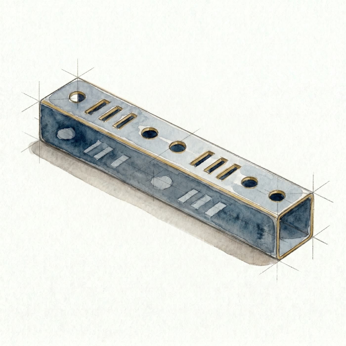
Cuts must be perpendicular and full-depth
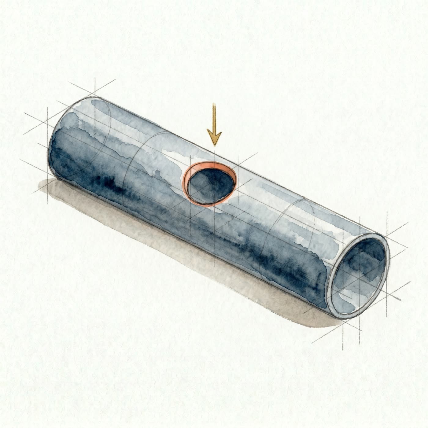
The tube laser cuts straight through one wall at a time. Every feature has to be perpendicular to the tube surface at the point of contact — no angled cuts, no partial-depth slots, no pockets. If you need angled features, model them as a perpendicular cut whose footprint matches what an angled cut would produce.
Square & rectangular tube: external corner radius
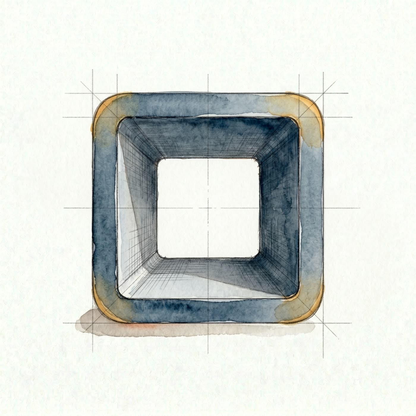
Drawn-over-mandrel and welded square / rectangular tube doesn't have a sharp 90° outside corner — there's a radius left by the forming rolls. Model that radius on the OD so the part nests cleanly to the stock. Industry rules of thumb:
- Steel and stainless tube: external corner radius ≈ 3× wall thickness
- Aluminum tube: external corner radius ≈ 0.5× wall thickness
Then offset the wall thickness inward to get the inside profile. If your stock supplier publishes specific corner-radius numbers, use those instead.
Tube modeled along the Y axis
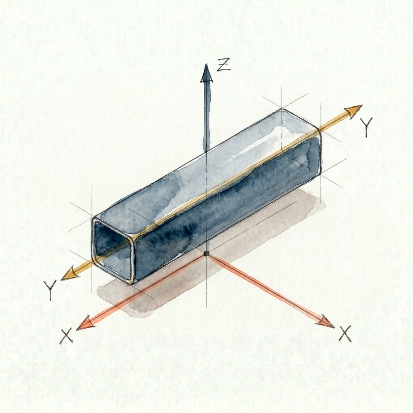
Align the tube so its length runs along the global Y axis, with one end at the origin. Auto-quote uses that convention to figure out start position, chuck location, and feature distances. If you model along X or Z, the file will still ingest, but the auto-quote may flip the part orientation and your callouts will end up on the wrong face.
Bridge cutouts that would drop a feature
The tube laser doesn't return drop-through scrap. If a cutout fully encloses an island — like an "O" shape, or a window with a tab in the middle — the inside piece falls through during cutting. Add bridges, or treat the design as a stencil.
Minimum hole and cutout
Same rule as flat sheet: holes and cutouts on the tube wall should be at least 50% of the wall thickness. So a tube with a 0.083″ wall wants ~0.040″ minimum holes. Anything smaller risks a failed pierce.
Materials & envelope
| Spec | Range |
|---|---|
| Profiles | Round, square, rectangular |
| Max OD (round) / W or H (square / rect) | 8″ |
| Max length | 30 ft |
| Common materials | Mild steel (A500, A513, DOM), stainless (304, 316), aluminum (6061), 4130 chromoly |
| Wall thickness | 0.049″ – 0.250″ typical; thicker walls quoted on request |
If your part needs a tube spec outside this envelope, drop it on your quote with a note — we'll source it.
Tolerances
| Feature | Default tolerance |
|---|---|
| Cut features (holes, slots, end profiles) | ±0.005″ |
| Feature-to-feature on the same cut | ±0.010″ |
| Overall part length | ±0.015″ |
| Cut-to-stock-end reference | ±0.020″ |
These are industry-typical defaults. Tighter tolerances are possible — call them out on the blueprint and we'll quote accordingly.
What to expect from finished tube parts
- Inside burrs / dross: the laser leaves some dross on the inside of the tube. Specify deburring on the blueprint if you need it removed.
- Weld seam: non-extruded square / rect tube has an internal weld seam. It may interfere with bridging or tabs; call out seam orientation if it matters.
- Conical taper: tube cuts have a small inherent taper, worse on thick walls and small diameters.
- No secondary ops on the tube line: taps, countersinks, dimples, hardware insertion — all happen on the sheet metal line and don't apply to tube parts.
Pre-flight checklist
- File is a STEP (.step or .stp); blueprint attached as supporting documentation
- Exactly one tube part per file (no assemblies)
- Tube modeled as a hollow tube at stock OD × wall × length
- 1:1 scale, inches or millimeters
- All cuts perpendicular to the tube surface and full-depth
- No multi-axis cuts, no blind pockets, no taps / countersinks
- Square / rect external corner radius modeled (≈ 3× wall for steel; ≈ 0.5× wall for aluminum)
- Tube length aligned along the +Y axis from origin
- Cutouts bridged if they'd drop a feature
- All holes / cutouts at least 50% of the wall thickness
- Material, OD, wall, length, finish, and tolerances called out on the blueprint
Ready to drop in your tube parts?
Upload your STEPs and blueprints. Up to 100 parts auto-quoted in minutes.
Get parts →